A Reference Architecture for Developers - Web 2.0 ArchitecturesTable of Contents
 About Reference ArchitecturesIn general, a reference architecture is a generic and somewhat abstract blueprint-type view of a system that includes the system’s major components, the relationships among them, and the externally visible properties of those components. A reference architecture is not usually designed for a highly specialized set of requirements. Rather, architects tend to use it as a starting point and specialize it for their own requirements. Models are abstract, and you can’t implement, or have an instance of, an abstract thing. Reference architectures are more concrete. They have aspects that abstract models do not, including cardinality (a measure of the number of elements in a given set), infrastructure, and possibly the concept of spatial-temporal variance (adding time as a concept). Consider again the example of residential architecture. The domain of residential dwellings has both an implied model and a reference architecture for a class of things called “houses.” The implied model for a house is composed of or aggregated from the following components:
This model for a house is minimalist and very abstract. It doesn’t detail such things as the type or number of floors, the height of the ceilings, the type of electrical system, and other things that become relevant only when a more concrete architecture (perhaps expressed as a set of blueprints) is made based on a specific set of requirements, such as “a residential dwelling in Denver for a family of five” or “a one-bedroom apartment in Berlin for an elderly person.” Although this model is very abstract, we can add details to each item in the reference architecture. For example, we can specify that the foundation be built in the shape of a rectangle. Other aspects in the reference architecture become more concrete if we then specialize the model for human inhabitants. For example, the floor must be edged by exterior walls of sufficient height to allow humans to walk through the house without stooping, and interior walls must be constructed to separate the rooms of the house based on their purposes. A reference architecture expressed as a set of generic blueprints based on the model discussed at the beginning of this section will be insufficient to actually build a modern residential dwelling. It doesn’t contain sufficient detail to serve as a set of builder’s plans. However, an architect can take the reference architecture and specify additional details to create the kind of plan that builders need. For example, the architect can specify the correct energy conduit to account for North American electricity delivery standards, design the interior floor plan based on the requirements of the house’s inhabitants, and so on. In sum, a reference architecture plays an important role as a starting point upon which more specialized instances of a class of thing can be built, with particular purposes and styles addressed as needed. The Web 2.0 Reference Architecture, therefore, can provide a working framework for users to construct specialized Web 2.0 applications or infrastructures from specific sets of requirements. We’ll explore that architecture next. The reference architecture shown in Figure 5.1, “Basic Web 2.0 Reference Architecture diagram” is an evolution of the abstract Web 2.0 model discussed in Chapter 4, Modeling Web 2.0, with more detail added for developers and architects to consider during implementation. Each layer can contain many components, but at the top level of abstraction, they provide a foundation that applies to many different kinds of application. The components of this architecture are:
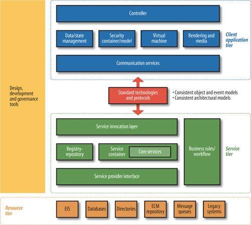
Each of these tiers can contain a wide variety of components. Figure 5.2, “Detailed reference architecture for Web 2.0 application architects and developers (special thanks to Nabeel Al-Sharma, Dan Heick, Marcel Boucher, Laurel Reitman, Kevin Lynch, and Michele Turner for help developing this model)” shows many more possibilities in greater detail. (Tools come in so many forms that it’s not easily broken down.) Figure 5.2. Detailed reference architecture for Web 2.0 application architects and developers (special thanks to Nabeel Al-Sharma, Dan Heick, Marcel Boucher, Laurel Reitman, Kevin Lynch, and Michele Turner for help developing this model) This Web 2.0 Reference Architecture is very general, but it fulfills a purpose similar to that of the residential dwelling reference architecture discussed earlier. It should not be considered “the” sole authoritative Web 2.0 Reference Architecture. It is meant asa reference architecture that decomposes each of the concepts in Figure 5.1, “Basic Web 2.0 Reference Architecture diagram” into more detail. Software architects or businesspeople can use it as a starting point when designing a way to implement a certain set of design or architectural patterns over the Internet. It lets those people ask important questions that will be relevant to their purposes, such as “What type of client application do we need?” or “Where are we going to authenticate users?” The Web 2.0 Reference Architecture is not tied to any specific technologies or standards nor is it dependent upon them. Architects and entrepreneurs can decide how to implement this reference architecture using standards and technologies specific to their needs. For example, if services need to be reachable by and visible to the largest possible segment of users, they may choose a protocol such as HTTP for its simplicity, its ability to pass through most corporate firewalls, and its widespread adoption. They could also opt for other messaging protocols to meet special requirements, such as Web Services Reliable Exchange (WS-RX) for reliable messaging, Web Services Secure Exchange (WS-SX) for enhanced security and efficiency with security, or BitTorrent for rapid distribution of multimedia content. One last thing to note is that software implementations may choose to use all, some, or none of the individual components in each of the tiers. Figure 5.2, “Detailed reference architecture for Web 2.0 application architects and developers (special thanks to Nabeel Al-Sharma, Dan Heick, Marcel Boucher, Laurel Reitman, Kevin Lynch, and Michele Turner for help developing this model)”is based on a commonly used set of components to enable the patterns described in Chapter 7, Specific Patterns of Web 2.0, but there are many simpler and more complex components that could be included. This tier contains core functionality and capabilities and can be implemented in many ways depending upon the context. For example, a large enterprise might have an ERP system, an employees directory, a CRM system, and several other systems that can be leveraged and made available as services via the service tier. A smaller example might be an individual cell phone with a simple collection of vCards (electronic business cards), which are also resources and can also be made available as a service to be consumed, perhaps over a Bluetooth connection. Figure 5.3, “Detail view of the resource tier” shows a fairly complex enterprise resource tier. The resource tier is increasingly being integrated into web applications in order to build rich user experiences. As client-side applications become richer and software rises above the level of any one piece of hardware (or device), making small computational pieces available to the client tier becomes a tangible requirement for many resource owners. This manifests as software that is no longer tied to specific operating systems or even, with large enterprise systems, operating in the cloud. While these inner boxes are meant only as exemplars of potential resources, we’ll look at each in detail to help you understand the overall architecture and some common capabilities:
At the core of the service tier (shown in Figure 5.4, “Detail view of the service tier”) is a service container, where service invocation requests are handled and routed to the capabilities that will fulfill the requests, as well as routing the responses or other events, as required. (Java programmers will be familiar with the servlet container model, for example.) The service container is a component that will assume most of the runtime duties necessary to control a service invocation request and orchestrate the current state, data validation, workflow, security, authentication, and other core functions required to fulfill service requests. In this context, a service container is an instance of a class that can coordinate and orchestrate service invocation requests until the inevitable conclusion, whether successful or not. Figure 5.4, “Detail view of the service tier” illustrates several elements within the service tier:
Service containers are the physical manifestation of abstract services and provide the implementation of the internal service interfaces. This can require substantial coordination. If, for example, a service request proves to be outside the service policy constraints, the service container might be required to generate a fault and possibly roll back several systems to account for the failed invocation request, as well as notifying the service invoker. The service container depicted in Figure 5.4, “Detail view of the service tier” might also use the registry/repository to help in service fulfillment. Additionally, the core service tier ties into backend capabilities via the SPI. Implementers of Web 2.0–type applications will have to consider the following integration questions while designing their systems, some of which will affect how the SPI is configured and what protocols it must handle:
There are other complications as well. Service interaction patterns may vary from a simple stateless request/response pair to a longer-running subscribe/push. Other service patterns may involve interpretation of conditional or contextual requests. Many different patterns can be used to traverse the service tier, and the semantics associated with those patterns often reside with the consumer’s particular “view.” For example, if a person is requesting a service invocation to retrieve data, he may define that service pattern as a data service. From a purely architectural perspective, however, this is not the case, because every service has a data component to it (for more specifics on the relationship between a service and data, see the discussion of the SOA pattern in Chapter 7, Specific Patterns of Web 2.0). Another person with a more specific view might try to define the service as a financial data service. This is neither right nor wrong for the consumer, as it likely helps her to understand the real-world effects of the service invocation. However, the granularity and purpose of the service pattern is in the eye of the beholder. Service oregistries are central to most SOAs. At runtime they act as points of reference to correlate service requests to concrete actions, in much the same way the Windows operating system registry correlates events to actions. A service registry has metadata entries for all artifacts within the SOA that are used at both runtime and design time. Items inside a service registry may include service description artifacts (WSDL), service policy descriptions, XML schemas used by various services, artifacts representing different versions of services, governance and security artifacts (certificates, audit trails), and much more. During the design phase, business process designers may use the registry to link together calls to several services to create a workflow or business process. Service registries help enterprises answer the following questions:
This is only a starter set of questions; you may come up with many more. The SOA registry/repository is a powerhouse mechanism to help you address such questions. It’s also worth discussing the service invocation layer in Figure 5.4, “Detail view of the service tier” in greater detail. The service invocation layer is where service invocation requests are passed to the core service container. The service invocation layer can hook into messaging endpoints (SOAP nodes, Representational State Transfer interfaces, HTTP sockets, JMS queues, and so on), but service invocations may also be based on events such as a timeouts, system failures and subsequent powerups, or other events that can be trapped. Client software development kits (SDKs), customer libraries, or other human or application actor interactions can also initiate invocation requests. In short, remember that several potential types of invocations are inherent in SOA design and to fulfill the patterns of Web 2.0 flexibility should be maintained by using the service invocation layer as a sort of “bus” to kick off service invocations. Realizing that patterns other than request/response via SOAP (what many people consider to be SOA) may be employed to invoke services will result in a much more flexible architecture. The client application tier of the Web 2.0 Reference Architecture, shown in Figure 5.5, “Detail view of the client application tier”, contains several functional components that are managed by the controller, the core application master logic and processing component. Every client application has some form of top-level control. The concept used here is in alignment with the controller concept in the Model-View-Controller (MVC) pattern. Web 2.0 clients often have several runtime environments. Each runtime is contained and facilitated by a virtual machine. Thus, while the runtime environments are launched and managed by a single controller, they remain somewhat autonomous with respect to executing scripts or bytecode to control certain aspects of an application. The virtual machine itself is a specialized type of controller, but it’s controlled by a master controller that’s responsible for launching and monitoring virtual machines and runtime environments as they’re required. To clarify the relationships, let’s break out each component in the client application tier diagram, starting at the top:
The client-side rendering engine handles all the “view” behavior for GUIs, as well as media integration. Rendering engines also pass information to the virtual machines and are controlled by the master controller. The data/state management mechanisms in the client tier control transformations, state synchronizations, transitions, and state change event generation during the object life cycle. On client systems, allowing access to local resources—even read-only privileges—represents a primary security risk. A sandbox philosophy typically confines the runtime environment and keeps it separate from the local system. Access to local system resources is usually denied unless explicitly granted for browser-based applications, unlike desktop applications, which enjoy a greater deal of interaction. There’s also a new breed of hybrid smart client applications that exist outside the browser, without being full-featured applications. Examples include widgets, gadgets, and Adobe’s AIR applications. These applications use a hybrid security model that must be carefully thought out, as smart client and composite applications that mash up content from more than one site can experience runtime problems with mismatched security privileges between domains. The communication services manage all communications, including between the client and server, with the host environment, and with resources in other tiers. Together with data/state management services, the communication services must be aware of the connection status and understand when to locally cache data and where to go to synchronize data states once interrupted connections are reestablished. Several of the patterns discussed in Chapter 7, Specific Patterns of Web 2.0, such as theSynchronized Web and Mashup patterns, require a careful orchestration of these resources. The SOA and MVC architectural models are key pillars of Web 2.0. The services tier and the client application tier must be built using similar design principles so that they can provide a platform for interaction. Resource tier and client application tier designers tend to abide by the core tenets and axioms of the Reference Model for SOA and apply application design principles such as MVC. The MVC paradigm encourages design of applications in such a way that data sets can be repurposed for multiple views or targets on the edge, as it separates the core data from other bytes concerned with logic or views. MVC, documented in detail at http://en.wikipedia.org/wiki/Model-view-controller, is a paradigm for separating application logic from the data and presentation components. MVC existed long before Web 2.0, but it can be usefully applied in many Web 2.0 applications and architectures. It’s a deployment pattern whereby application code is separated into three distinct areas: those concerned with the core data of the application (the Model), those concerned with the interfaces or graphical aspects of the application (the View), and those concerned with the core logic (the Controller). MVC works across multiple tiers: it allows application reskinning without affecting the control or data components on the client, and it enables Cloud Computing, where virtualization results in the controller and model concerns being distributed in opaque regions while still fulfilling their required roles. Web 1.0 applications tended to mix together the Model, View, and Controller. Early applications were built around requests for specific pages, with every page a program of its own and data linked primarily by SQL calls to shared databases. On the client, HTML scrambled behavior with view and processing. Although HTML used different elements for these functions, the result was still a mixed-up markup language. Web application development has evolved, however. On the client, HTML still provides a basic framework, but it has become more of a container for parts that support the different aspects of MVC more cleanly. While the HTML itself still often contains much information, XML and JSON offer data-only formats that clients and servers can use to communicate their data more precisely, according to models created early in development. (This makes it easier for other users or applica |
手机版|小黑屋|BC Morning Website ( Best Deal Inc. 001 )
GMT-8, 2026-7-10 18:53 , Processed in 0.018608 second(s), 18 queries .
Supported by Weloment Group X3.5
© 2008-2026 Best Deal Online